Name of Project: PE Exam Timer
Date Project Completed: 07/20/2016
Grade: 4

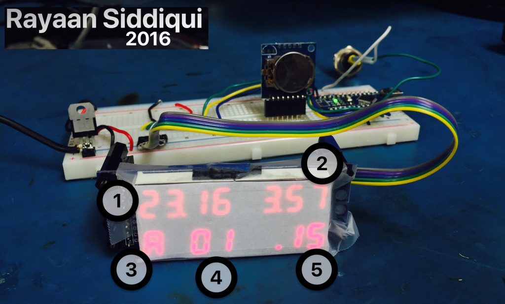
This project helps people taking the PE (Principles and Practice of Engineering exam) Exam effectively manage their time. My Inspiration for this project was that my mother(who is a Civil Structural Engineer) was taking the PE (Principles and Practice of Engineering exam). Digital and Analog Clocks were allowed on the test, but there were no clocks designed specifically for the exam. This clock shows which question the test taker should be on, the current time, the time left per question, the amount of time in the session remaining, and the session of the exam (the first 4 hour session or the latter). 

Please refer to the numbers in the image above:

1: The Current Time. In the picture the time was 23:16, or 11:16.
2: How much time is left in the session. There are two four-hour sessions in the PE exam.
3: There are 2 four-hour sessions, so session A represents the first session and session B represents the second session.
4: The question the test taker should be on.
5: Time left in the current question.

Above is a schematic I made (using Fritzing) describing the components on the device: 

1: Battery Pack. Powers the device without having to plug in to the wall.
2: 7-segment LED displays and MAX-7219 Serial 8-digit LED Display Driver. MAX-7219 allows the eight-digit LEDS to be controlled by arduino. The serial interface on MAX-7219 reduces the amount of wires, without it there would be much more wires.
3: Arduino Nano. This is the microcontroller that is the “brain of the whole system”. It gets the time from the RTC Moudule, sends information to the LED 7-segment displays, and  detects button presses. The Arduino Nano was coded using the Arduino IDE.
4: This is a power regulator (L7805). The power regulator provides the circut 5 Volts regardless of how many Volts the Battery provides. This ensures the Arduino and the 7 Segment display run correctly.
5: This is the Real Time Clock Module (DS1307). The RTC module keeps the time and date by running even when the battery is off and the circuit is not running. It has its own battery which allows it to continue counting the time even when it is not recieving any power.

I changed the battery from 2 AA batteries to a lithium ion battery and the power regulator to an AdaFruit LiIon/LiPoly charger. This way the device can be recharged using an industry-standard microUSB cable rather than replacing its batteries.

Build one yourself:
Use the schematic and my .ino code file file below to make your own PE Exam Timer (Step-by-Step Guide coming soon).

Images of Project (you can click to enlarge):